7-Segment Display – Introduction, Types and Interfacing with Arduino
7-Segment Display – Introduction, Types and Interfacing with Arduino
These type of displays are found in many day-to-day applications. Let’s discuss what are they and their types. Also, its interfacing with Arduino.
A 7-segment display has the lowest price amongst all types of displays. It is widely used in devices that shows numerical information.
You may have seen the 7-segment display in counter machines, fancy shop banners, etc.
To display alphabets and symbols, opting-in for LCD would be the best choice.
But the fact is LCDs are costlier than LED displays. And, due to this reason most people prefer to opt-in for LED displays for basic requirements like displaying numbers.
In this article, you will learn the interfacing of the 7-segment display with Arduino.
But we will start with the basics so that you will understand how these displays work.
Table of Contents
Now without any further ado, let’s start,
What is a 7-Segment Display?
A 7-segment display is nothing but a pack of seven LEDs connected together where each LED is known as a segment. All of them can be controlled individually.
You might be wondering how these seven LED’s are connected together to work as a display.
Let me explain,
There are two 7-segment LED display configurations,
- Common Cathode
- Common Anode
(We will discuss these configurations later in this article.)
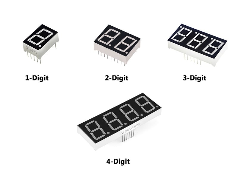
7-Segment displays are available in various colors (Red, Blue, and Green) and sizes (0.56 to 6.5 inches). Sometimes two to four 7-segment displays are packed together to form a big display (refer to following image).

Few of the 7-segment displays has 8 LEDs. It is in the form of an additional circular LED on board, as shown in following image. The circular LED indicates decimal point in numeral.

7-Segment Display Types
Depending upon the LED anode and cathode connections 7-segment displays are divided into two types.
We will discuss these two types and their configurations briefly,
1. Common Cathode (CC)
As the name itself speaks a lot, all cathode terminals are connected together, and anode terminals are left open.
To use this type of 7-segment display you need to connect cathode to GND terminal and anode to 5V supply.
2. Common Anode (CA)
All anode terminals are connected, and cathode terminals are kept open.
To turn on the LED display, connect anode to 5V supply and cathode to GND.
Interfacing 7-segment Display with Arduino
Each LED in 7-segment display is connected separately to GPIO pins on Arduino board.
For interfacing purpose let we consider a common anode (CA) 7-segment display.
As the anode is the common terminal here so let us connect it to the 5V supply on Arduino. The remaining pins will be connected to the GPIO pins on Arduino.
We will be using separate wiring (refer to the connection diagram) for each LED segment and turn on the display in an ornate fashion.
Truth Table for 7-Segment Display
Refer to following Truth Table to understand the code logic.
Code for turning ON all the LEDs one by one
void setup()
{
  // define pins as an output pins

 pinMode(2,OUTPUT);
 pinMode(3,OUTPUT);
 pinMode(4,OUTPUT);
 pinMode(5,OUTPUT);
 pinMode(6,OUTPUT);
 pinMode(7,OUTPUT);
 pinMode(8,OUTPUT);

}

void loop()
{
  // loop to turn on the led

  for(int i=2;i<9;i++)
  {
    digitalWrite(i,HIGH);
    delay(1000);
  }

  // loop to turn on the led
  for(int i=2;i<9;i++)
  {
    digitalWrite(i,LOW);
    delay(1000);
  }


  delay(1000);

}
There are two “for” loops in above code for switching each LED segment ON and OFF.
Initially, all of the pins are high (all LEDs will glow). After an interval, the first “for” loop will come into action, and each LED will start glowing one by one.
Once the cycle completes, the second “for” loop will come into action and turn OF all the LED segments.
You can add more delay to see results on display more clearly.
Code for displaying digits/numbers
If you are familiar with the arrays in C++, you will quickly understand the following code. But no worries if you don’t.
Copy-paste the code below without any modification.
// make an array to save Sev Seg pin configuration of numbers

int num_array[10][7] = {  { 1,1,1,1,1,1,0 },    // 0
                          { 0,1,1,0,0,0,0 },    // 1
                          { 1,1,0,1,1,0,1 },    // 2
                          { 1,1,1,1,0,0,1 },    // 3
                          { 0,1,1,0,0,1,1 },    // 4
                          { 1,0,1,1,0,1,1 },    // 5
                          { 1,0,1,1,1,1,1 },    // 6
                          { 1,1,1,0,0,0,0 },    // 7
                          { 1,1,1,1,1,1,1 },    // 8
                          { 1,1,1,0,0,1,1 }};   // 9

//function header
void Num_Write(int);

void setup()
{
  // set pin modes
  pinMode(2, OUTPUT);
  pinMode(3, OUTPUT);
  pinMode(4, OUTPUT);
  pinMode(5, OUTPUT);
  pinMode(6, OUTPUT);
  pinMode(7, OUTPUT);
  pinMode(8, OUTPUT);


}

void loop()
{

  //counter loop

  for (int counter = 10; counter > 0; --counter)
  {
   delay(1000);
   Num_Write(counter-1);
  }
  delay(3000);
}

// this functions writes values to the sev seg pins
void Num_Write(int number)
{
  int pin= 2;
  for (int j=0; j < 7; j++) {
   digitalWrite(pin, num_array[number][j]);
   pin++;
  }
}
Conclusion
So that is it. If you are doing this project then don’t forget to come back and share your 7-segment LED project with us.
It is an excellent Arduino based project for beginners. One can also use the 7-segment display in projects that need to display numbers.
Thanks for reading till the end. If you have any doubts, then ask me. I will be glad to help you out.


