Tinkercad to Create a Temperature Monitoring Circuit with Arduino
Tinkercad to Create a Temperature Monitoring Circuit with Arduino
Tinkercad is a web-based circuit design and simulation tool that allows users to create and test electronic circuits without the need for physical components. It simplifies the learning and experimentation process with electronics and programming, providing easy access from any device and location. This platform is particularly beneficial for beginners and hobbyists seeking a user-friendly and favourable option for their projects. Tinkercad has a variety of electronic components, used to construct circuits and control various devices. Additionally, the platform has a built-in Arduino simulator, enhancing its capabilities.
Configuring TinkerCad for Design & Simulation
- Go to the Tinkercad website
- Create an account: If you don’t have an account, sign up for a free account on Tinkercad.
- Create a new project: Once you’re logged in, create a new project and choose “Circuits” as the project type.

Circuit Design of Temperature Monitoring: Tinkercad
We have to design and simulate a temperature monitoring circuit inside Tinkercad where we will learn how to use a design interface and connect electronic components like an Arduino board and a temperature sensor with LCD Display. Additionally, we will program & simulate our circuit to get the Output.
The circuit designing interface is very straightforward. Need to just follow the basic steps:
- At the right sidebar you’ll find a wide range of electronic components.
- Drag and drop the Required components:
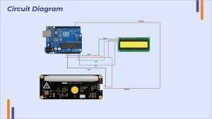
- Make the connections according to the below-specified diagram, connect the components by clicking on their connectors and dragging wires between them.

Arduino Code to Program Temperature Monitoring System
After finishing the circuit design, go to the code editor located on the right side, and choose “text code”. Place your code with the correct pinouts and included libraries.
Below one is the code used to simulate the created design. You can make necessary changes like pins, and display manner.
Temperature Monitoring Circuit Simulation: Tinkercad
Once you’ve designed and programmed your circuit, click the “Start Simulation” button to see your Arduino board in action and test the behavior of your circuit. Now, you will see that the Temperature can be monitored on a Serial monitor as well as on LCD Display. That’s how you can observe the circuit’s output behavior.

What’s the difference between Real and Virtual Circuit Simulation
As you have seen the virtual circuit design, simulation, and output result, but on the other side, what if the same circuit is physically designed and simulated? For that, we created the same circuit with all the same connections.

Changes Made Inside Code: The only change you have to make in the physical connection is the Address for the I2C display which must be correct to be detected by Arduino.
LiquidCrystal_I2C lcd(0x20, 16, 2); changed to LiquidCrystal_I2C lcd(0x27, 16, 2);
Live Demonstration of Arduino Temperature Monitoring Circuit
Actual hardware simulation provides a distinct and valuable real-time experience compared to virtual simulations like Tinkercad. Connections, power supply, and wiring must be handled with precision and care when working with physical components. Real-time deployment can sometimes lead to errors and challenges related to wiring connections, requiring effective troubleshooting to overcome the problems. Finally, you see that the temperature is displaying very well.


