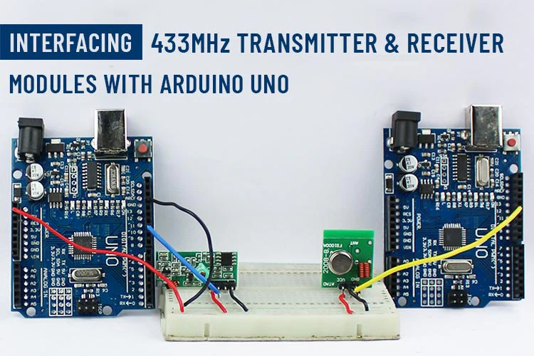
Interfacing 433MHz Transmitter and Receiver Modules with Arduino UNO
A 433MHz transmitter and receiver pair uses Amplitude Shift Keying (ASK) modulation to transmit and receive data wirelessly. The transmitter modulates a 433MHz carrier wave with the data signal using an ASK modulator, and transmits the modulated signal through an antenna. The receiver picks up the transmitted signal with an antenna, filters out unwanted signals, and demodulates the signal to recover the data. The range of the wireless communication system depends on factors such as the transmit power, antenna gain, and the presence of obstacles or interference.
COMPONENTS REQUIRED
To build a basic 433MHz transmitter and receiver system, you will need the following components:
- 433MHz Tx and Rx Module
- Arduino uno
- Breadboard
- Connecting wires
- Power Supply
TRANSMITTER HARDWARE
A 433MHz transmitter is a device use in radio waves to send signals over a frequency of 433 Mhz. It is commonly used in wireless remote control systems and wireless security systems to transmit data over short distances. The transmitter consists of a circuit board with a transmitter chip, antenna, and other components to modulate and amplify the signal..
433MHz Transmitter Pinout

The pinout of a 433MHz transmitter may vary depending on the specific model or manufacturer. However, most 433MHz transmitters have at least three pins:
VCC or VDD: This is the power supply pin and is usually connected to a 5V power source.
GND: This is the ground pin and is usually connected to the ground or negative terminal of the power supply.
DATA or SIGNAL: This is the pin that is used to send the digital signal throught transmitter chip. It is usually connected to a microcontroller or other device that is sending the signal.
RECEIVER HARDWARE
A 433 MHz receiver is an electronic device used for receiving signals in the 433 MHz frequency band. It’s commonly used in wireless communication systems, remote control devices, and security systems, and requires connection to a microcontroller or other processing circuitry to operate.
433MHz Receiver PINOUT

A typical 433MHz receiver has three pins: VCC, GND, and DATA.
The pinout might be vary slightly depending on the specific module, but here is a common pinout:
VCC: This pin is used to supply power to the module. Typically, it requires a voltage between 3.5V and 5V DC.
GND: This pin is used as the ground reference for the module.
DATA: This is the signal output pin, which sends digital data to the microcontroller or other receiving device. The output data is usually in the form of a pulse-width modulation (PWM) signal, with a pulse duration that corresponds to the incoming signal.
AMPLITUDE SHIFT KEYING (ASK)

Amplitude Shift Keying (ASK) is a popular modulation technique used in low-cost wireless communication systems due to its simplicity and cost-effectiveness. ASK is widely used in applications such as remote controls, wireless sensors, and wireless doorbells.
The ASK technique is based on varying the amplitude of the carrier wave according to the data signal. The carrier wave is usually a high-frequency sine wave, such as a 433 MHz signal. When a digital ‘1’ is to be transmitted, the amplitude of the carrier wave is increased, while no signal is transmitted for a digital ‘0’. This produces a square wave-like signal that can be transmitted over the air.
One of the advantages of ASK is its simplicity of this. ASK transmitter and receiver circuits are straight forward and can be built using simple components such as resistors, capacitors, and transistors. Additionally, ASK modulation requires less bandwidth than other modulation techniques, which makes it suitable for low-data-rate applications.
However, ASK is susceptible to interference from other radio sources and ambient noise. This can lead to poor signal quality and transmission errors. To minimize the effect of interference, ASK transmitters and receivers can be designed to include filters and error-correction coding.
In summary, Amplitude Shift Keying (ASK) is a simple and cost-effective modulation technique used in low-data-rate wireless communication systems.
THE RADIOHEAD PACKET
RadioHead is an open-source software library for low-power wireless communication, used with small embedded systems like Arduino. The RadioHead packet is a data structure that encapsulates the data to be transmitted wirelessly. The packet includes a header and payload section. The library provides functions for creating, sending, and receiving RadioHead packets. It supports ASK, FSK, and OOK modulation techniques, as well as popular hardware platforms. It simplifies low-level wireless communication, allowing developers to focus on application logic.
To install the library, launch the Arduino IDE, navigate to Sketch > Include Library > Add.ZIP Library, and then choose the RadioHead file you just downloaded.
CIRCUIT DIAGRAM – 433MHz Transmitter and Arduino Uno

Here you can see that Arduino uno connected with 433 mhz transmitter. where vcc connected with 5v of battery and ground connected GND. Data pin connected with 11 port .

Arduino Code
| // Include RadioHead Amplitude Shift Keying Library #include <RH_ASK.h> // Include dependant SPI Library #include <SPI.h> // Create Amplitude Shift Keying Object RH_ASK rf_driver; void setup() { // Initialize ASK Object rf_driver.init(); } void loop() { const char *msg = “quartz component”; rf_driver.send((uint8_t *)msg, strlen(msg)); rf_driver.waitPacketSent(); delay(1000); } |
Code Explanation
Include RadioHead Amplitude: Shift Keying Library: This line includes the RadioHead ASK library, which is required to use the ASK modulation technique for wireless communication.
Include dependant SPI Library: This line includes the SPI library, which is required by the RadioHead library for communication with the hardware.
Create Amplitude Shift Keying Object: This line creates an object named “rf_driver” of the RH_ASK class, which is used to control the ASK wireless transmitter and receiver.
Setup function: This function runs once when the Arduino board is powered on or reset. It initializes the ASK object.
Loop function: This function runs repeatedly after the setup function has completed. It sends a wireless message every second.
Create message: This line creates a pointer to a character array containing the message “quartz component”.
Send message: This line sends the message using the ASK object. It converts the message to a byte array and sends it over the wireless channel.
Wait for packet to be sent: This line waits for the ASK object to finish sending the packet before moving on to the next iteration of the loop.
Delay: This line causes a delay of 1000 milliseconds (1 second) before the loop repeats and sends the next message.
CIRCUIT Diagram – 433MHz Receiver and Arduino Uno

Here you can see that Arduino uno connected with 433 mhz receiver. where vcc connected with 5v of battery and ground connected GND. Data pin connected with 12 port.

Arduino Code
| // Include RadioHead Amplitude Shift Keying Library #include <RH_ASK.h> // Include dependant SPI Library #include <SPI.h> // Create Amplitude Shift Keying Object RH_ASK rf_driver; void setup() { // Initialize ASK Object rf_driver.init(); // Setup Serial Monitor Serial.begin(9600); } void loop() { // Set buffer to size of expected message uint8_t buf[11]; uint8_t buflen = sizeof(buf); // Check if received packet is correct size if (rf_driver.recv(buf, &buflen)) { // Message received with valid checksum Serial.print(“Message Received: “); Serial.println((char*)buf); } } |
Code Explanation
Include RadioHead Amplitude Shift Keying Library: This line includes the RadioHead ASK library, which is required to use the ASK modulation technique for wireless communication.
Include dependant SPI Library: This line includes the SPI library, which is required by the RadioHead library for communication with the hardware.
Create Amplitude Shift Keying Object: This line creates an object named “rf_driver” of the RH_ASK class, which is used to control the ASK wireless transmitter and receiver.
Setup function: This function runs once when the Arduino board is powered on or reset. It initializes the ASK object and sets up the serial monitor to communicate with the computer.
Loop function: This function runs repeatedly after the setup function has completed. It listens for incoming wireless messages and prints them to the serial monitor.
Set buffer size: This line creates an array named “buf” with a size of 11 bytes, which is the maximum size of an expected message.
Check for incoming message: This line checks if there is an incoming message on the wireless channel. If there is, it stores the message in the buffer and sets the value of “buflen” to the size of the message.
Print message: This line prints the received message to the serial monitor.
Cast buffer to string: This line casts the buffer from a byte array to a string using typecasting, so it can be printed as text.
The code listens for incoming messages on the wireless channel and prints them to the serial monitor. If there is no incoming message, the loop function simply repeats.
Serial Monitor Output


