Real Time Heart Rate Monitoring System Using Arduino
Real Time Heart Rate Monitoring System Using Arduino
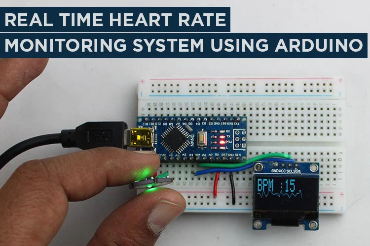
This project is an Arduino-based heart pulse sensor that uses an OLED display to show the user’s pulse rate. The program uses an analog heart rate sensor connected to pin A0 of the Arduino board. The code reads the sensor values and maps them to a range between 0 and 45 to create a graph that shows the user’s pulse rate. The program also calculates the user’s BPM (beats per minute) and displays it on the OLED screen. The user’s BPM is calculated by measuring the time between high pulses (values above 540) and storing the number of counts per minute. The program clears the graph and restarts the measurement every 128 data points. The program uses the Adafruit_GFX and Adafruit_SSD1306 libraries to control the OLED display.
Components Required
Features of the Pulse Sensor and OLED Display
Pulse Sensor:
Analog Sensor: The pulse sensor is an analog sensor that measures the changes in blood volume in the finger or earlobe.
Non-Invasive: The pulse sensor is a non-invasive device that does not require any penetration of the skin.
Easy to Use: The pulse sensor is easy to use and can be attached to a finger or earlobe using a clip or strap.
OLED Display:
High Contrast: The OLED display provides high contrast and sharp images, even in low light conditions.
Low Power Consumption: The OLED display consumes very low power and can be used with battery-powered device.
High Resolution: The OLED display provides high resolution and can display text, graphics, and animations with great detail.
Pulse Sensor Pinout

Pulse sensor that is used to measure the electrical activity of the heart. This sensor can connected to an Arduino or any other microcontroller to monitor and display heart rate data.
The pin diagram of an ECG sensor typically includes three pins: VCC, GND, and OUT.
VCC pin: This pin is used to supply power to the sensor. It is typically connected to the 3.3V pin on the Arduino board.
GND pin: This pin is used to connect the sensor and the ground of the Arduino board.
OUT pin: This pin is used to transmit the measured heart rate data to the Arduino board.
Working of Pulse Sensor
A heartbeat sensor used to detect the heart rate of an individual by measuring the changes in blood volume during each heart beat. The sensor usually consists of an IF LED and a photodetector, and is placed on a fingertip. When the LED emits light into the tissue then blood absorbs some of the light and the remaining light is detected by the photodetector place in it.
As the heart pumps blood through the body, the blood volume in the fingertip increased and decreased with each beat. This changes in the amount of light detected by the photodetector, resulting in a pulsating signal that corresponds to the individual’s heart rate. The sensor then converted the pulse signal into an electrical signal which is then processed to display on the screen.
OLED Display Pinout

OLED (organic light-emitting diode) displays are a type of display technology that can uses organic compounds to spread light when an electric current is passed through them.
The pin diagram of an OLED display typically includes four pins: VCC, GND, SDA, and SCL.
1 VCC pin: This pin is used to supply power to the OLED display. It is typically connected to the 5V pin on the Arduino board.
2 GND pin: This pin is used to connect the OLED display to the ground of the Arduino board.
- SDA pin: This pin is used for data transmission in I2C communication. It is typically connected to the A4 pin on the Arduino board.
- SCL pin: This pin is used for clock signal in I2C communication. It is typically connected to the A5 pin on the Arduino board.
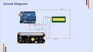
Circuit Diagram

Here we use Arduino Nano and oled ,heart beat sensor .we connect heart beat sensor with Arduino Nano with A0 with signal pin .vcc with 3.3v and ground with GND. Here we connect oled with vcc with 5v and ground with vcc .SCL connect with A5 and SDA with A4 .

Arduino Code for Interfacing Pulse Sensor with Arduino
This code is for a heart pulse sensor with Arduino and an OLED display. The program reads analog data from the sensor and displays the pulse rate in beats per minute (BPM) on an OLED display. The sensor data draw a pulse graph on the display.
The code begins with including the required libraries such as SPI, Wire, Adafruit_GFX, and Adafruit_SSD1306. The Adafruit_SSD1306 library is used to control the OLED display. The next line of code initializes the Adafruit_SSD1306 object with the display size set to 128×32 pixels.
| #include <SPI.h> #include <Wire.h> #include <Adafruit_GFX.h> #include <Adafruit_SSD1306.h> Adafruit_SSD1306 circuit = Adafruit_SSD1306(128, 32, &Wire); Next, the code defines the sensor pin as A0 and sets the high pulse value to 540. The high pulse value is the value above which the program will count a pulse beat. #define sensor A0 #define Highpulse 540 Next, some variables are initialized to set the starting position of the pulse graph and store the pulse values. int sX = 0; int sY = 30; int x = 0; int Svalue; int value; long Stime = 0; long Ltime = 0; int count = 0; int Bpm = 0; |
In the setup() function, the serial communication is initiated, and the OLED display is initialized with the command circuit.begin(SSD1306_SWITCHCAPVCC, 0x3C) where SSD1306_SWITCHCAPVCC is the display voltage and 0x3C is the I2C address of the display. A delay of 1000 milliseconds is added to allow the OLED display to initialize. The clearDisplay() function is used to clear any previous display data.
| void setup() { Serial.begin(9600); circuit.begin(SSD1306_SWITCHCAPVCC, 0x3C); delay(1000); circuit.clearDisplay();} |
In the loop() function, the program reads the analog value from the pulse sensor and maps it to a value between 0 and 45. The mapped value is used to set the Y position of the pulse graph. The X position is incremented by one in each loop, and the pulse graph is drawn using the draw Line() function. The BPM value is displayed on the OLED display using print() and setCursor() functions.
| void loop() { Svalue = analogRead(sensor); Serial.println(Svalue); value = map(Svalue, 0, 1024, 0, 45); int y = 30 – value; if (x > 128) { x = 0; sX = 0; circuit.clearDisplay(); }circuit.drawLine(sX, sY, x, y, WHITE); sX = x; sY = y; x ++; BPM(); circuit.setCursor(0, 0); circuit.setTextSize(2); circuit.setTextColor(SSD1306_WHITE); circuit.print(“BPM :”); circuit.print(Bpm); circuit.display(); } |
Error in Interfacing pulse sensor – Here is what you Should do?
- Error occurring when pulse sensor is show very low response .then I will change threshold value upto 540.its works.
- Error occurring when I saw bpm value not change rapidly .its ok because it take to compile then whole program..
Complete Code
| /*Heart pulse sensor with Arduino and OLED display */ #include <SPI.h> #include <Wire.h> #include <Adafruit_GFX.h> #include <Adafruit_SSD1306.h> Adafruit_SSD1306 circuit = Adafruit_SSD1306(128, 32, &Wire); // Change OLED display size to 128×32 #define sensor A0 #define Highpulse 540 int sX = 0; int sY = 30; // Change Y position of the pulse graph to make room for BPM display int x = 0; int Svalue; int value; long Stime = 0; long Ltime = 0; int count = 0; int Bpm = 0; void setup() { Serial.begin(9600); circuit.begin(SSD1306_SWITCHCAPVCC, 0x3C);// Address 0x3C for 128×32 delay(1000); circuit.clearDisplay(); } void loop() { Svalue = analogRead(sensor); Serial.println(Svalue); value = map(Svalue, 0, 1024, 0, 45); int y = 30 – value; // Change Y position of the pulse graph to make room for BPM display if (x > 128) { x = 0; sX = 0; circuit.clearDisplay(); } circuit.drawLine(sX, sY, x, y, WHITE); sX = x; sY = y; x ++; BPM(); circuit.setCursor(0, 0); circuit.setTextSize(2); circuit.setTextColor(SSD1306_WHITE); circuit.print(“BPM :”); circuit.print(Bpm); // Display BPM value instead of count circuit.display(); } void BPM() { if (Svalue > Highpulse) { Stime = millis() – Ltime; count++; if (Stime / 1000 >= 60) { Ltime = millis(); Serial.println(count); Bpm = count; // Store BPM value instead of count count = 0; } } } |


