Arduino based Tachometer (RPM Meter) using IR sensor
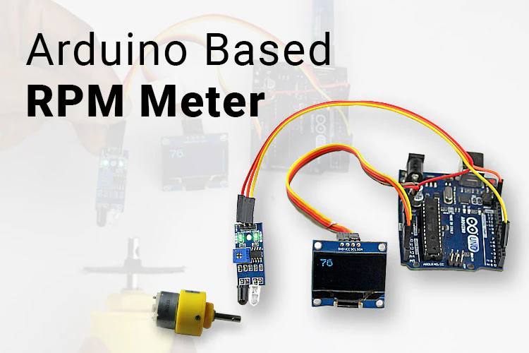
In this tutorial, we are going to make Digital Tachometer using an IR Sensor with the help of Arduino for measuring the number of rotations of the rotating Motor in RPM. Here we have interfaced the IR sensor module with Arduino and the 0.96 Inch OLED display to display the RPM count. The IR sensor module consists of an IR Transmitter & Receiver that can work as a Digital Tachometer for speed measurement of any rotating object. There are two types of tachometer one is mechanical and another one is digital. Here we are going to build an Arduino-based digital tachometer using an IR sensor module. So let’s make it.
Software Required
- Arduino IDE
Circuit
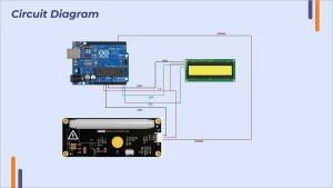
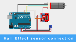
Follow this table to make your connections.
| IR module pins | Arduino pins |
| Vcc | 3.3 V |
| OUT | 2 |
| GND | GND |
| OLED pins | Arduino pins |
| Vcc | 5V |
| SDA | A4 |
| SCL | A5 |
| GND | GND |
Arduino Source Code
Here is a code for Digital Tachometer using IR Sensor and Arduino. Simply copy the code and upload it to your Arduino board using Arduino IDE software.
| #include <Arduino.h> #include <U8x8lib.h> #include <SPI.h> #include <Wire.h> U8X8_SSD1306_128X64_NONAME_HW_I2C u8x8(/* reset=*/ U8X8_PIN_NONE); unsigned long rpmtime; float rpmfloat; unsigned int rpm; bool tooslow = 1; void setup() { u8x8.begin(); u8x8.setFont(u8x8_font_profont29_2x3_f); TCCR1A = 0; TCCR1B = 0; TCCR1B |= (1 << CS12); //Prescaler 256 TIMSK1 |= (1 << TOIE1); //enable timer overflow pinMode(2, INPUT); attachInterrupt(0, RPM, FALLING); } ISR(TIMER1_OVF_vect) { tooslow = 1; } void loop() { delay(1000); if (tooslow == 1) { u8x8.clear(); u8x8.drawString(1, 0, “SLOW!”); } else { rpmfloat = 120 / (rpmtime/ 31250.00); rpm = round(rpmfloat); u8x8.clear(); u8x8.setCursor(1,0); u8x8.print(rpm); } } void RPM () { rpmtime = TCNT1; TCNT1 = 0; tooslow = 0; } |
Troubleshooting
Project not working?
Ensure that the circuit you have made is according to the circuit . Check for loose connections.
IR sensitivity issue?
There is a potentiometer on the IR sensor module. Adjust with the help of screwdriver as per your requirement.
OLED not showing values?
Ensure that OLED must be supplied with the proper voltage value. It works on I2C communication protocol.
SDA (Serial Data) – The line for the master and slave to send and receive data.
SCL (Serial Clock) – The line that carries the clock signal.
.


