Security Alarm using HC-SR501 PIR Sensor and Arduino
Security Alarm using HC-SR501 PIR Sensor and Arduino
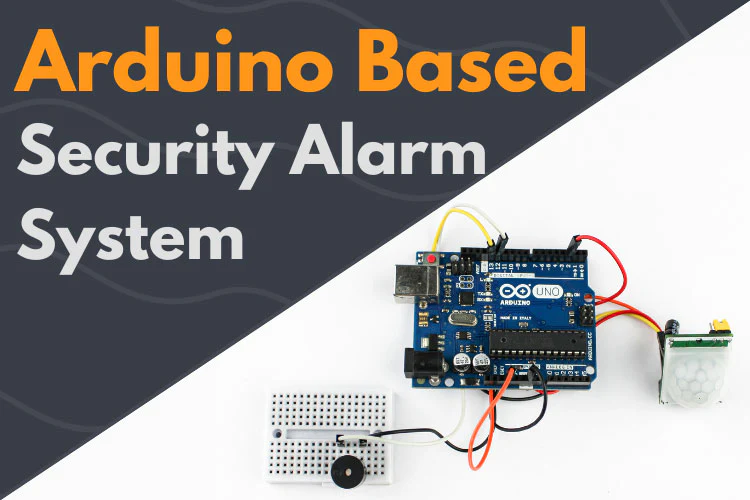
In this Arduino tutorial, we are going to learn how to use a motion sensor to sound a piezoelectric buzzer. The motion sensor used here is a PIR sensor which stands for Passive Infrared Sensor. This is great for an intrusion detection circuit or burglar alarm circuit. Whenever the motion sensor senses movement the piezoelectric buzzer will make an audible sound.
PIR Sensor Pinout

PIR Datasheet
| Model no | HC- SR501 |
| Offset Voltage | 0.3v – 1.2v |
| Supply Voltage | 3-15v |
| Operating Temp. | -30 to 70 degree Celsius |
| Sensitivity | >3300V/M |
PIR Working Principle
What is a PIR Sensor?
PIR stands for Pyroelectric Infrared Sensor or Passive Infrared Sensor. PIR is an electronic sensor that detects the changes in the infrared light across a certain distance and gives out an electrical signal at its output. It can detect any infrared-emitting object such as human beings or animals if it is within the range of the sensor, or moves away or within the range of the sensor.
Trigger modes:-
We have two trigger modes in the PIR sensor one is non-repeat mode and repeat mode trigger. These two modes can be obtained by changing the jumper position given in the corner of the module.
Non-repeat Mode:
When we use PIR in this mode, the output will go HIGH for the stipulated time and then turn LOW.
For example, If Output turns HIGH for 10 seconds, it will turn LOW after this time period.
Repeat Trigger Mode:
In this mode when motion is detected the output will remain HIGH till it is observing motion, whether the motion is by single person or multiple person.
Block Time:
Block time is a period when the PIR sensor does not detect any motion. It is nearby for 3 seconds. After this block time, the PIR is ready to work again.
Delay Time Adjustment :
There is a potentiometer to adjust the output to remain HIGH after detecting the motion. We can adjust the time period from 5 seconds to 5 minutes.
Sensitivity Adjustment:
A potentiometer is given to adjust the sensitivity. We can vary it from 3 meters to 7 meters perpendicular to the sensor. The sensitivity reduces as we move either side of the sensor. The angle of the detection area of PIR is around 110 degrees conic section.
Components Required
Security Alarm Circuit Diagram

In the above circuit diagram, the GND of the PIR sensor is connected to the GND Pin of the Arduino board. PIR is powered by the 3.3V supply of Arduino. The output of the sensor is connected to Arduino Pin no. 2. Arduino Pin no. 13 is taken as the output and hence connected to the buzzer. Buzzer ground is connected to the Arduino ground terminal. Now we are ready to upload the code.
Arduino Code for Security Alarm
| void setup() { pinMode(2, INPUT); //Pin 2 as INPUT via sensor pinMode(13, OUTPUT); //PIN 13 as OUTPUT to buzzer } void loop() { if (digitalRead(2) == HIGH) { digitalWrite(13, HIGH); // turns the Buzz ON delay(100); // wait for 100 msecond digitalWrite(13, LOW); // turns the Buzz OFF delay(100); // wait for 100 msecond } |
Code Explanations
| In the void setup function, we are declaring pin no. 2 as a Input via PIR sensor and pin no. 13 as a output to buzzer. void setup() { pinMode(2, INPUT); //Pin 2 as INPUT via sensor pinMode(13, OUTPUT); //PIN 13 as OUTPUT to buzzer } In the void loop function, there is a loop, so whenever the condition satisfies, the output goes HIGH and LOW after the delay of every 100 milliseconds and hence we attain a desired output. void loop() { if (digitalRead(2) == HIGH) { digitalWrite(13, HIGH); // turns the Buzz ON delay(100); // wait for 100 msecond digitalWrite(13, LOW); // turns the Buzz OFF delay(100); // wait for 100 msecond } |
Other sensors/Alternatives RCWL-0516 Micro Wave RADAR Sensor
RCWL-0516 is a widely popular sensor that also detects movements and is used in Alarms or for security purposes. This sensor uses a “microwave Doppler radar” technique to detect moving objects within its range. It has a sensitivity range of up to 7 meters and that is very useful for multiple applications.
Ultrasonic Sensor Module – HC-SR04
The Ultrasonic Sensor uses Ultrasonic waves to determine the distance of an object, hence it can be used as a distance measuring sensor. It measure distance of 2cm to 400cm. They are cheap, easy to interface and require low power to operate and has a multiple application.
PIR Troubleshooting
No power supply!
There might be a probability that your PIR sensor is not connected to the supply properly. You are required to check all the connections again. Identify the loose connections.
PIR not working properly!
There is a Fresnel lens in front of a PIR sensor. Clear off the dust with acetone and cotton.
Error while uploading code!
Ensure that your Arduino Board is working properly and do not got toasted with your previous project. Also, have a look over the code. It should follow the correct procedure.
Want to control sensitivity and time delay of the sensor?
With the help of potentiometer knob you can control these two parameters.
No sound in buzzer?
Do cross-check the buzzer whether it is in working condition or not by directly supplying 5volts to it. If it sounds that means the buzzer is in working condition.
Caution: Always use active buzzer when working with arduino as it needs DC supply to operate.


