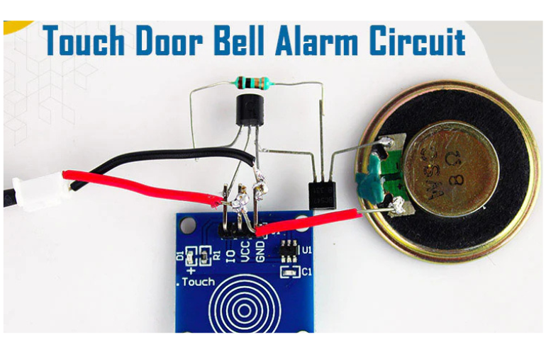


In this tutorial, we are going to make a Touch Door Bell Alarm Circuit which will sound a melody with just a touch of a finger. This project uses a TTP223 capacitive touch sensor module which gives input to the musical IC that is amplified by NPN transistor and hence melody is played on the speaker. Let’s make this Project.

| Model No. | BC 547 |
| DC Current Gain (hFE) | Min: 110 Max:800 |
| Collector Current (IC) | 100 mA |
| Collector Power Dissipation | 500 mW |
| Collector-Base Voltage (VCBO) | Max: 50V |
| Collector-Emitter Voltage (VCEO) | Max: 45V |
| Emitter-Base Voltage (VEBO) | Max: 6V |
| Junction Temperature | 150 °C |
| Storage Temperature | -65 ~ 150 °C |

| Operating Voltage | Min: 1.3V Max: 3.3V |
| Supply current | 1uA |
| Frequency Operating | Min: 57Hz Max: 82Hz |
| Operating Temperature | -20 to 65 oC |

When the touch sensor is touched a 3.7V signal is generated at the IO pin of the sensor. This pin is connected to the Vdd of Musical IC. Its output pin is connected to the Base of a transistor that acts as an amplifier and hence a melody is created and can be heard by the speaker.
BT66 is easy to use three-terminal Melody generator IC. It can be used where the tone has to be played as a notifier. It consumes very little current (1uA) hence increasing battery life. There are many applications of this melody IC. In case you want a different tone you have to use a different IC with a different Model number. In our case, we are using BT66T-68L.
| S.No | IC Model Number | Tone name |
| 1 | BT66T-02L | Jingle Bell |
| 2 | BT66T-19L | For Elise |
| 3 | BT66T-08L | Happy Birthday |
| 4 | BT66T-12L | Love Story |
| 5 | BT66T-68L | It’s a Small World |

In the above circuit diagram, the touch sensor module has three pins. Vcc is supplied with a positive of 3.7v battery. GND is connected to the negative terminal of the battery. Its signal pin is connected to the Vdd terminal (or Vcc terminal) of Musical IC.
UM66 has 3 pins too whose GND is connected to GND its output is fed into the base of the transistor. This transistor is acting as an amplifier. The transistor emitter terminal is connected to the GND and its collector terminal is connected to the negative of the speaker. The positive of the speaker is connected to the Battery’s positive terminal. In this way, our circuit connection is done.
Ensure that your circuit is according to the circuit diagram and you must check BJT, touch sensor and Melody IC that they must be in good working condition.
The Battery used here is 3.7 volts. Less than this voltage rating, the circuit may malfunction.
Yes, we can use a higher rating of the speaker like 0.5 watts. You will get a louder sound but it will consume more power.
In this condition check your touch sensor with a multimeter. Apply 3.7 volts to the Vcc pin and connect ground to ground. Now take a multimeter and connect the positive probe to the OUT pin and the Negative probe to GND. Now touch a sensor, if the Multimeter shows output on touching that means it is in good working condition.
.
An all order above 499
UPI, Debit, Credit, Netbanking
Whatsapp us at +91 9080968234
Support timings:
Mon-Sat 10.00 am to 5.00 pm
Orders more than 1000 INR for free delivery..... COD Orders only available for more than 500 INR purchases only. Dismiss