DIY Smart Blind Stick using Arduino and Ultrasonic Sensor
DIY Smart Blind Stick using Arduino and Ultrasonic Sensor
In this project, we will be using an ultrasonic sensor, buzzer, vibration motor to build an Arduino based smart blind stick, which can find any object coming towards it and alert the person holding the stick..
Components Required
- Arduino Nano – 1
- Ultrasonic Sensor -1
- Buzzer – 1
- BC547 transistor – 1
- Micro coin vibration motor – 1
- Breadboard – 1
- Resistor – 100 Ohm – 1
- 9V battery – 1
- Connecting wires
Ultrasonic Sensor
The working of ultrasonic sensor is simple to understand. If a transmitter is generating a sound at t = 0 sec, and a receiver is receiving that same signal after some time period, let’s say T sec. We know the speed of the sound (343 m/S), if we multiply the speed of the sound with the time taken for the signal to reach the receiver, we can find that distance traveled by the signal. By using this same concept, the ultrasonic sensor works and determines the object’s distance, which is placed in front of it.
When coming to its specifications, the operating voltage of the ultrasonic sensor is 5V and consumes a current of less than 15mA. The ultrasonic sensor consists of 4 pins. The Vcc and GND pins are connected to the 5V and GND of the power supply. The trig pin is the pin on which we will be generating the sound (by giving pulse) and the echo pin is the pin on which we will be checking the change in its logical state. So depending on the code, we need to connect the pins accordingly.

Micro coin Vibration motors
These micro coin vibration motors may sound new to you, but in fact, these are the common component in your watches, mobile phones, joysticks, etc. These types of motors are generally used for discrete alerts, precision alarms, etc. The vibration motors are similar to the conventional DC motors. The rotating mass is placed in an off-center position to the point of rotation. By doing this, these motors produce an uneven centripetal force which causes to and fro motion (vibrations). When it comes to its specifications, the motor operating voltage ranges from 2.5V to 4V. Its maximum rated current is 90mA. There are only two terminals for the motor. The red wire is connected to the positive terminal, and the blue wire is connected to the negative terminal of the power supply.

Piezoelectric Buzzer
The principle behind the working of piezoelectric material is that, whenever an electric potential is applied across a piezoelectric material, the internal pressure variation is generated. This continuous change in its pressure variation will pull one conductor and push other conductors continuously. These continuous pull and push lead to generating a sharp sound wave. When it comes to its specifications, its operating voltage ranges from 3-20V, it takes a current of value less than 15mA. It consists of two pins. There will be an indication(+ mark) on top of the buzzer, connect this side of the pin to the positive terminal of the power supply. The pin opposite to it is connected to the negative terminal of the power supply.

BC547 transistor
The regions of operation of a transistor are, saturation region, active region, inverse active region, and cutoff region. In our project, we will be using our transistor as a switch, so it must operate in the saturation region. When it comes to the pin configuration, it consists of 3 pins. Collector, Base, and Emitter. If you are facing the flat surface of the transistor, the leftmost pin is the collector, the middle pin is the base, and the rightmost pin is the emitter pin.

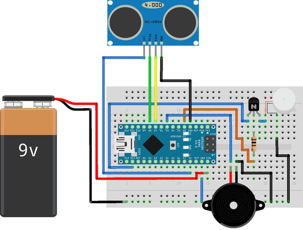
Arduino Blind Stick Circuit Diagram
We need to connect the ultrasonic sensor, buzzer, vibration motor through the transistor to Arduino Nano. Let us first connect the ultrasonic sensor with Arduino nano. The Vcc and GND pins of the ultrasonic sensor is connected to the 5V and GND pin of the Arduino nano. The trig and echo pin of the ultrasonic sensor is connected to the D7 and D8 pin of the Arduino nano. Now, let us connect the piezoelectric buzzer with Arduino nano. The positive terminal of the buzzer is connected to the D5 of the Arduino nano and the negative terminal of the buzzer is connected to the GND pin of the Arduino. Now, the vibration motor is connected to the Arduino through a transistor. As the motor operating voltage is 2.5V to 4V, we are using the transistor as a switch. The transistor collector terminal is connected to the 3v3 pin of the Arduino and the emitter terminal is connected to the posting terminal of the motor. The negative terminal of the motor is connected to the GND. the base of the transistor is connected to the D2 pin of the Arduino nano through a 100-ohm resistor. A battery of 9V is used to power the whole module. The positive terminal of the battery is connected to the Vin pin of the Arduino nano and the negative terminal of the battery is connected to the common ground as shown in the below circuit diagram.
Arduino Smart Blind Stick Code Explanation
At first, we will simplify things by providing names to the pins. After that, we will be setting the pins trigPin, buzz and biv pin as output pins, and pin echoPin as an input pin.
const int trigPin = 8;
const int echoPin = 7;
const int buzz = 5;
const int vib = 2;
void setup() {
pinMode(trigPin, OUTPUT); // Sets the trigPin as an Output
pinMode(echoPin, INPUT); // Sets the echoPin as an Input
pinMode(buzz, OUTPUT);
pinMode(vib, OUTPUT);
Serial.begin(9600); // Starts the serial communication
}
Inside the void loop, at first, we will generate a pulse of ON period of 10 uS. Then we will check for the logic change on the pin echoPin by using the pulseIn() function. The pulseIn () function returns the time taken for the soundwave to travel in microseconds. By using the formula we will then find the distance of the object, which is placed in front of the ultrasonic sensor.
void loop() {
// Clears the trigPin
digitalWrite(trigPin, LOW);
delayMicroseconds(2);
// Sets the trigPin on a HIGH state for 10 microseconds
digitalWrite(trigPin, HIGH);
delayMicroseconds(10);
digitalWrite(trigPin, LOW);
// Reads the echoPin, returns the sound wave travel time in microseconds
duration = pulseIn(echoPin, HIGH);
// Calculating the distance
distance= duration*0.034/2.0;
// Prints the distance on the Serial Monitor
Serial.print(“Distance: “);
Serial.println(distance);
Here, we will check if the distance. If the distance is less than 70 cm, it means that an object is near or approaching the blind person. We have to inform the blind person beforehand that there is an object in front of him. To make the blind person aware of it, we will be producing a beep sound using a buzzer. The beep sound gets fast if the distance between the object and the blind person keeps on decreasing. Along with the beep sound, we will produce vibration on the stick. It will make the holder of the stick to alert fast.
if (distance < 70)
{
Serial.print(distance);
Serial.println(“Object Alert”);
digitalWrite(vib, HIGH);
digitalWrite(buzz,HIGH);
delay(100);
digitalWrite(buzz,LOW);
digitalWrite(vib, LOW);
for (int i= (distance-40); i>0; i–)
delay(10);
}
}
Working of Arduino Blind Stick Project
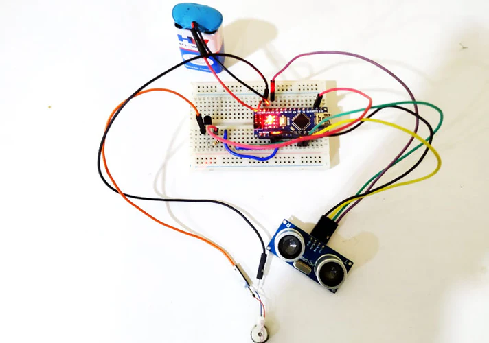
After building, your project will be looking somewhat like this.

For testing, you can try and walk with it at your home. If any object comes in a range of 50cm, the buzzer will start, indicating that there is an object near the person. To provide an additional alert, the stick will start vibrating, just like a mobile phone in vibration mode.
Smart Blind Stick Arduino Code
| const int trigPin = 8; const int echoPin = 7; const int buzz = 5; const int vib = 2; // defines variables long duration; float distance; void setup() { pinMode(trigPin, OUTPUT); // Sets the trigPin as an Output pinMode(echoPin, INPUT); // Sets the echoPin as an Input pinMode(buzz, OUTPUT); pinMode(vib, OUTPUT); Serial.begin(9600); // Starts the serial communication } void loop() { // Clears the trigPin digitalWrite(trigPin, LOW); delayMicroseconds(2); // Sets the trigPin on HIGH state for 10 micro seconds digitalWrite(trigPin, HIGH); delayMicroseconds(10); digitalWrite(trigPin, LOW); // Reads the echoPin, returns the sound wave travel time in microseconds duration = pulseIn(echoPin, HIGH); // Calculating the distance distance= duration*0.034/2.0; // Prints the distance on the Serial Monitor Serial.print(“Distance: “); Serial.println(distance); if (distance < 70) { Serial.print(distance); Serial.println(“Object Alert”); digitalWrite(vib, HIGH); digitalWrite(buzz,HIGH); delay(100); digitalWrite(buzz,LOW); digitalWrite(vib, LOW); for (int i= (distance-40); i>0; i–) delay(10); } } |


