HMC 5883L Triple Axis Magnetometer with Arduino?
HMC 5883L Triple Axis Magnetometer with Arduino?
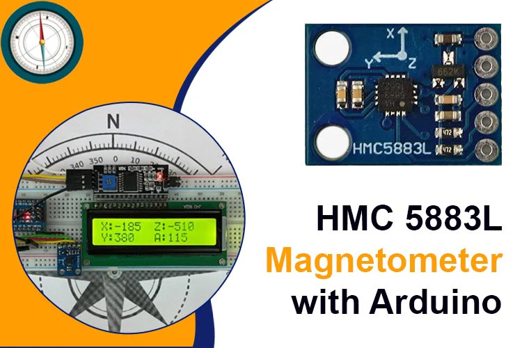
The HMC5883L is a magnetometer used for measuring magnetic fields. It is widely used, affordable, and capable of detecting magnetic fields in its environment. The HMC5883L sensor offers precise and dependable measurements, making it suitable for compass navigation, orientation sensing, and detecting magnetic fields.
HMC5883L Sensor
| Pin Number | Pin Name | Description |
| 1 | VCC | Input voltage from +3V to +6V (Typically 5V) |
| 2 | GND | Connected to the Ground of the circuit |
| 3 | SCL | Serial Clock Pin. Connect this pin to the A5 or SCL pin of the Microcontroller. |
| 4 | SDA | Serial Data Pin. Connect this pin to the A4 or SDA pin of the Microcontroller. |
| 5 | DRDY | Data Ready Pin Output. Interrupt Pin |
Features of HMC 5883L Magnetometer
- The input voltage range is from +3V to +6V.
- The sensor uses the QMC5883L IC.
- It can detect a magnetic field range from -8 to +8 Gauss with 2 mGauss resolution.
- The communication interface is I2C.
- It provides a heading accuracy of 1-2 degrees.
- The sensor has an integrated 12-bit ADC.
- The maximum data rate is 160Hz.
HMC 5883L Alternatives:
Brief about the Working of the HMC 5883L
The module consists of an HMC 5883L IC, a 662K voltage regulator IC, as well as capacitors and resistors integrated into a circuit. The HMC 5883L IC, which is produced by Honeywell, serves as the core component of this module.
The Honeywell HMC5883L is a surface-mount, multi-chip module designed for low-field magnetic sensing with a digital interface for applications such as low-cost compassing and magnetometry. The HMC5883L includes high-resolution HMC118X series magneto-resistive sensors plus an ASIC containing amplification, automatic degaussing strap drivers, offset cancellation, and a 12-bit ADC that enables 1° to 2° compass heading accuracy.
Note: You can read more about the module, its pin configurations and working in detail by referring to the original datasheet.
Circuit Diagram – Interface HMC 5883L with Arduino

Required Components
- HMC 5883L Triple Axis Magnetometer
- Arduino Nano
- 16×2 LCD Display
- I2C Serial Interface LCD Adapter Module
- Breadboard
- Jumper Wires
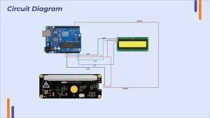
For interfacing the HMC 5883L, connect the module to Arduino in this manner. You can also connect an LCD to display the results or use the Serial Monitor for the same.
We have used the QMC 5883L Arduino Library. To download the library, follow these steps:
Note: The HMC 5883L module and QMC 5883L perform the same functions. The library however for each of them is different. We have used a QMC 5883L here, if you are using an HMC 5883L module, install the HMC 5883L library from the Libraries Section.
Go to Tools à Manage Libraries à Type “QMC 5883” on the Search Bar à Install the “QMC 5883L Compass” Library by MRP Programs.
Once you have installed the library, you can upload the following code to your Arduino Board. The output of the code will display X, Y and Z coordinates.
This code should do the trick, you will be able to see the X, Y and Z coordinates on your LCD screen and the Serial Monitor as well.

Applications of HMC 5883L Sensor
- Compass and heading tracking
- Gesture recognition
- Geolocation and GPS augmentation
- Magnetic field mapping and surveys


