How to make Incredible smoke detection and fire alarm system using MQ 135 Gas Detector Sensor, flame sensor and ESP32.
How to make Incredible smoke detection and fire alarm system using MQ 135 Gas Detector Sensor, flame sensor and ESP32.

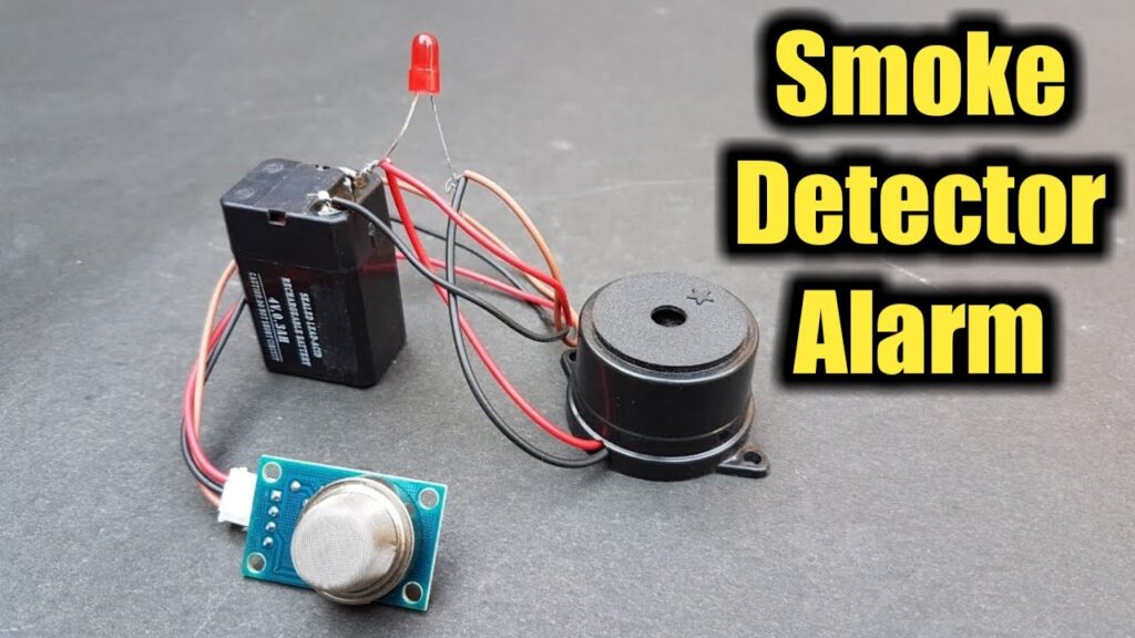
A easy DIY smoke detection and fire alarm system project using ESP32 ,gas detector MQ 135 and flame sensor which is integrated with Arduino IOT cloud provides remote monitoring. MQ
A easy DIY smoke detection and fire alarm system project using ESP32 ,gas detector MQ 135 and flame sensor which is integrated with Arduino IOT cloud provides remote monitoring.
MQ 135
- MQ 135 is Air Quality/Gas Detector Sensor
- MQ 135 can detect Ammonia, Sulphide, and Benzene steam, also sensitive to smoke and other harmful gasses from the desired distance.
- MQ 135 Air Quality/ Gas Detector Sensor has low conductivity in fresh air. When the combustible gas exists, the conductivity of the sensor is high along with the gas concentration rise.
- MQ 135 sensor Convert the change of conductivity to the corresponding output signal of according to gas concentration.
- We can use MQ 135 for air quality monitoring, air pollution detection, toxic gas detection, industrial pollution detection, portable air pollution detection.
- MQ 135 has 4 pins VCC ,GND,A0,D0 and it’s operating voltage is 2.5v-5v using this pin interfacing it with controller becomes easy .
Flame sensor
Flame sensor is nothing but IR detector
This sensor can detect flame or wavelength of the light source within 760nm~1100nm at the distance 80cm. and produces output at D0.
sensitivity of this sensor is adjustable with the help of potentiometer
It can be used in fire alarm systems and detection or any switching system.
Hardware Requirement
Software requirement
- Arduino IDE
- Arduino cloud Web
- Arduino IOT Remote App
- Arduino create agent for cloud
Creating thing and dashboard on Arduino cloud
let’s start creating Dashboard
- Create/login to Arduino cloud account
- Click on Things > CREAT THING

Click on Add variables

1st variable
Name > gas >Declaration> int gas Type> Integer number > Variable Permission> Read Only >Update Policy> On change
2nd variable
Name > flame>Declaration> int flame Type> Integer number > Variable Permission> Read Only >Update Policy> On change

Create all variables accordingly Select and configure associate device
Here we have Selected DOIT ESP32 DEVKIT V1 Once device is selected properly Device ID and Device Secret key will Displayed we have to save It Properly
After selecting the device, we have to configure the network. (Providing name and credential information of Wi-Fi or Hotspot & Device secrete key) to which we are supposed to connect our ESP32
Configure network >Wi-Fi Name>Wi-Fi Password>Device Secrete key

Create a dashboard
Let’s create a dashboard where our data will be displayed and Monitored
Follow the steps
Click on Dashboards > CREATE DASHBOARD > ADD

DD>GAUGE> Link variable > Things >Fire_Alarm>gas>LINK VARIABLE>DONE
ADD>GAUGE> Link variable > Things >Fire_Alarm>flame>LINK VARIABLE>DONE

Now Open Sketch in full Editor & edit the code according to variables

Download Arduino Create Agent & Connect ESP32 board
Select the proper Arduino Board and port
Verify and upload the code
Code and libraries
#include "arduino_secrets.h"

#include "thingProperties.h"
int gas_data=34;
int flame_data=35;

int Alarm=32;
int relay=33;
void setup() {

  Serial.begin(9600);

  delay(1500);
  pinMode(gas_data,INPUT);
   pinMode(flame_data,INPUT);
   pinMode(Alarm,OUTPUT);
   pinMode(relay,OUTPUT);
  // Defined in thingProperties.h
  initProperties();
  // Connect to Arduino IoT Cloud
  ArduinoCloud.begin(ArduinoIoTPreferredConnection);

  setDebugMessageLevel(2);
  ArduinoCloud.printDebugInfo();
}

void loop() {
  ArduinoCloud.update();
  // Your code here
  gas=analogRead(gas_data);
  flame=digitalRead(flame_data);
  if(gas>200){
    digitalWrite(Alarm,HIGH);
    delay(5000);
  }
  else if(flame<1){
    digitalWrite(relay,HIGH);
    delay(5000);
    digitalWrite(relay,LOW);
  }
  else{
    digitalWrite(Alarm,LOW);
    digitalWrite(relay,LOW);

  }
}

void onGasChange()  {

}

void onFlameChange()  {

}
thingProperties.h
#include <ArduinoIoTCloud.h>

#include <Arduino_ConnectionHandler.h>


const char DEVICE_LOGIN_NAME[]  = "";your device name(device ID)


const char SSID[]               = SECRET_SSID;    // Network SSID (name)

const char PASS[]               = SECRET_OPTIONAL_PASS;    // Network password (use for WPA, or use as key for WEP)

const char DEVICE_KEY[]  = SECRET_DEVICE_KEY;    // Secret device password


void onFlameChange();

void onGasChange();


int flame;

int gas;


void initProperties(){


  ArduinoCloud.setBoardId(DEVICE_LOGIN_NAME);

  ArduinoCloud.setSecretDeviceKey(DEVICE_KEY);

  ArduinoCloud.addProperty(flame, READWRITE, ON_CHANGE, onFlameChange);

  ArduinoCloud.addProperty(gas, READWRITE, ON_CHANGE, onGasChange);


}


WiFiConnectionHandler ArduinoIoTPreferredConnection(SSID, PASS);
arduino_secrets.h
#define SECRET_SSID "" // your Network SSID (name)

#define SECRET_OPTIONAL_PASS ""  // your Network password (use for WPA, or use as key for WEP)

#define SECRET_DEVICE_KEY "" // Secret device password
Libraries
If Arduino cloud is used for uploading code Arduino cloud agent will download all necessary libraries automatically
If not
Download
Necessary Libraries from Library manager of Arduino IDE
And make sure Arduino create agent for cloud is paused when code is upload in board from Arduino IDE
Same goes for Arduino cloud if code is uploading from Arduino cloud make sure Arduino IDE is closed.
Circuit diagram
Breadboard connections
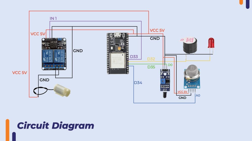
Test Connection are made according to circuit diagram we have connected gas sensor MQ 135 and Flame sensor to D34 and D35 of ESP 32 board with VCC and GND and relay to D33 with buzzer and LED (Alarm)to D32 pin .we have set threshold value MQ 135 and flame sensor and set condition for relay pin when sensor reading crosses this threshold value the signal is passed to relay pin, buzzer and LED by board the relay is turned ON which eventually operates water pump connected to relay and LED with buzzer also operates which shows alarm .This data is also integrated with cloud so it updates in real time on Arduino cloud dashboard and IOT remote app

Hardware interfacing
Working
The gas sensor MQ 135 and flame sensor are connected to controller with relay, buzzer and LED the threshold values are set for sensors with relay and buzzer in condition. When smoke or flame is detected the sensor reading crosses this threshold value which triggers the condition and signal is passed to relay and buzzer pin by controller. Relay and buzzer turn ON which leads to operating water pump. The sensor data is integrated to Arduino cloud, so it updates on its dashboard as well as IOT remote app we can monitor Realtime data

Conclusion
We have completed IOT based smoke detection and fire alarm project. This project has wide range of applications and advantages the implementation of this project can reduce Fire hazards and risk of unfortunate fire accidents. It be used in LPG gas leakage detection, air quality monitoring, air pollution detection, toxic gas detection, industrial pollution detection.


