Humidity Measurement Using Arduino Uno and DHT11
Humidity Measurement Using Arduino Uno and DHT11
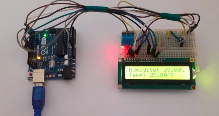
We need the temperature and humidity measurement to understand the environmental conditions for a given zone. We might use google or any whether predicting site for the same but often they do not show the real time data and most of the data is averaged out and often based on predicting algorithms. We might also need to measure temperature and humidity level of a closed chamber manufacturing process where controlling the temperature and humidity of a process is of utmost importance. In this project we will be using Arduino Uno and DHT11 Temperature and Humidity Sensor to measure the ambient temperature and humidity in the air and display the measured values on a 16×2 LCD screen.
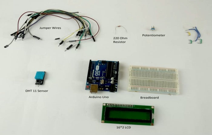
Components Required
DHT11 Working Principle
Now coming on to the working of the DHT11 sensor. It has an NTC Thermistor and a humidity measuring component on a PCB in it. For measuring humidity, they use the humidity sensing component which has two electrodes with moisture holding substrate between them. So as the humidity changes, the conductivity of the substrate changes or the resistance between the electrodes changes. This change in resistance is measured by the PCB connected to it and then is transmitted for reading to the controller. For measurement of Temperature it employs NTC (Negative Temperature Coefficient) Thermistor which has, as evident by name, a negative temperature coefficient, it means its resistance will decrease with increase in temperature and increase with decrease in temperature.

The PCB also measure this change in resistance and transmit the data to the microcontroller board in digital format. DHT11 gives us very precise value of humidity and temperature and ensures high reliability and long term stability. The temperature range of DHT11 is from 0 to 50 degree Celsius with a 2-degree accuracy. Humidity range of this sensor is from 20 to 80% with 5% accuracy. The sampling rate of this sensor is 1Hz .i.e. it gives one reading for every second. DHT11 is small in size with operating voltage from 3 to 5 volts. The maximum current used while measuring is 2.5mA.
DHT11 module works on serial communication i.e. single wire communication. This module sends data in form of pulse train of specific time period. Before sending data to arduino it needs some initialize command with a time delay. And the whole process time is about 4ms. A complete data transmission is of 40-bit and data format of this process is given below:
8-bit integral RH data + 8-bit decimal RH data + 8-bit integral T data + 8-bit decimal T data + 8-bit check sum.
For displaying the data received, we have used 16*2 LCD display. You can also use the serial monitor of the Arduino to display the readings coming from sensor on your monitor screen.

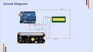
Arduino DHT11 Sensor Connection Diagram

Here we can see that the DHT11 sensor module is connected to Arduino by connecting Pin 1 (Vcc) to 5V power pin, Pin 3 (GND) is connected to GND of Arduino and Pin 2 (DATA) is connected to the Digital pin 2. For connecting 16*2 LCD screen connect VSS to GND, VDD to 5V supply, VO to the output of potentiometer to vary the contrast of the characters, RS to pin 0 on Arduino, RW to GND, E to pin 1 on Arduino. Now data lines D4, D5, D6 and D7 are connected to pin 8, 9, 10 and 11 pins respectively. Connect A to 5V supply via 220Ω resistor and connect K to GND.
LCD is connected to Arduino in 4 bit mode i.e. the Arduino and LCD are communicating in 4 bit at a time which is bit slower than 8 bit communication but as our DHT 11 has a sampling freq. of 1 Hz it will work just fine also it means less number of connecting wires and improved reliability.
Writing the Program
To write the Arduino DHT11 sensor interfacing code, we start with including the two libraries for LCD display and DHT11 sensor so that we don’t have to worry about reading and separating the data from the data stream coming through the sensor.
#include<dht.h> //To include a library to read data from dht11 sensor
#include<LiquidCrystal.h> //To include a library to write data on the 16*2 lcd device.
Now define the pins on the Arduino where we have connected the pins from 16*2 LCD and DHT 11 sensor.
LiquidCrystal lcd(0, 1, 8, 9, 10, 11); //we have connected LCD pins to these pins on Arduino board
#define dht_dpin 2 //DHT data pin is connected to pin 2 on the Arduino Board
After that we make a degree [ ̊ ] sign using custom characters (glyph) to be displayed on the LCD screen.
byte degree[8] =
{
0b00011,
0b00011,
0b00000,
0b00000,
0b00000,
0b00000,
0b00000,
0b00000
}; // This line is to create a custom Degree sign in degree celcius.
Now coming to the setup part we first initialize the 16*2 LCD and then start measuring the temp and humidity data from the sensor.
void setup() // this will run only on either on start-up or when arduino is reset
{
lcd.begin(16, 2);
lcd.createChar(1, degree); //we assign a number 1 to the degree sign created above
lcd.clear();
lcd.print(“Temp & Humidity”);
lcd.setCursor(0,1);
lcd.print(” Measurement “); // Print the words Humidity Measurement on LCD screen
delay(2000); // Keep the words on screen for two seconds
lcd.clear(); // clear the screen for writing anything else
lcd.print(” Quartz “);
lcd.setCursor(0,1);
lcd.print(” Components “);
delay(2000);
}
Then we start a loop to display the incoming reading from the sensor in proper format which will refresh every half a second.
void loop() // this function will keep on running
{
DHT.read11(dht_dpin); // This command will read the incoming data from the DHT11 sensor
lcd.setCursor(0,0); // Setting Curser on First character of first line
lcd.print(“Humidity: “); // printing the word Humidity: on the display
lcd.print(DHT.humidity); // printing Humidity value we got from the Sensor on the LCD
lcd.print(“%”);
lcd.setCursor(0,1); // setting curser on First character on 2nd line
lcd.print(“Temp: “);
lcd.print(DHT.temperature); // Printing temperature reading we got from Sensor on the LCD
lcd.write(1); // Write the custom charecter we created (degree sign)
lcd.print(“C”);
delay(500); // refresh every half second
}
Arduino DHT11 Sensor Code to Display the Sensor Data on 16×2 LCD
| #include<dht.h> //To include a library to read data from dht11 sensor #include<LiquidCrystal.h> //To include a library to write data on the 16*2 lcd device. LiquidCrystal lcd(0, 1, 8, 9, 10, 11); //we have connected LCD pins to these pins on Arduino board #define dht_dpin 2 //DHT data pin is connected to pin 2 on the Arduino Board dht DHT; byte degree[8] = { 0b00011, 0b00011, 0b00000, 0b00000, 0b00000, 0b00000, 0b00000, 0b00000 }; // This line is to create a custom Degree sign in degree celcius. void setup() // this will run only on either on start-up or when arduino is reset { lcd.begin(16, 2); lcd.createChar(1, degree); //we assign a number 1 to the degree sign created above lcd.clear(); lcd.print(“Temp & Humidity”); lcd.setCursor(0,1); lcd.print(” Measurement “); // Print the words Humidity Measurement on LCD screen delay(2000); // Keep the words on screen for two seconds lcd.clear(); // clear the screen for writing anything else lcd.print(” Quartz “); lcd.setCursor(0,1); lcd.print(” Components “); delay(2000); } void loop() // this function will keep on running { DHT.read11(dht_dpin); // This command will read the incoming data from the DHT11 sensor lcd.setCursor(0,0); // Setting Curser on First character of first line lcd.print(“Humidity: “); // printing the word Humidity: on the display lcd.print(DHT.humidity); // printing Humidity value we got from the Sensor on the LCD lcd.print(“%”); lcd.setCursor(0,1); // setting curser on First character on 2nd line lcd.print(“Temp: “); lcd.print(DHT.temperature); // Printing temperature reading we got from Sensor on the LCD lcd.write(1); // Write the custom charecter we created (degree sign) lcd.print(“C”); delay(500); // refresh every half second } |


