Interfacing IR Proximity Sensor with Arduino
Interfacing IR Proximity Sensor with Arduino
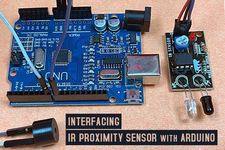
An IR sensor module has two important parts: an IR transmitter LED and an IR receiver LED. The transmitter LED sends out invisible infrared light, and if this light bounces off an object in front of it, the receiver LED detects it. The IR module is used in many DIY projects, like line-following robots, and devices that sense & and spot objects. It works by emitting and detecting IR light to figure out if something is in its way and then responds accordingly.
Specifications:
- Operating Supply voltage: 5 volts
- Detection Range: Up to 20cm.
- Operating Current: Approx 20mA
- Output Signal: Usually LOW when there’s no object
- I/O pins are 5V and 3.3V compliant
- Adjustable Sensing range
The general common pins on such a module are:
VCC (Power Supply Voltage): This pin is used to provide power to the module which requires a voltage of 5V.
GND (Ground): Pin used to connect to the ground (0V) of your Arduino.
OUT (Signal Output): This pin provides the digital output signal from the module. When an object is detected within the sensor’s range, it typically goes HIGH and when no object is detected, it goes LOW.
IR Transmitter LED: Emits infrared light (usually with a wavelength of around 940nm).
IR Receiver LED: Detects reflected infrared light.
LM358 IC: It is an inbuilt Op-Amp comparator IC which is used as a control circuitry in combination with Resistances.
Potentiometer(10k): To adjust the Sensitivity of the module, but it will also affect the Range.
Indicator LED: Indicates the output of the Op-Amp IC. Usually glows at HIGH output.
Interfacing Circuit for IR Sensor with Arduino
The sensor module is capable of detecting objects through IR reception, and it provides a signal on its output pin to indicate whether an object is detected. We have integrated a buzzer to produce a sound whenever the sensor detects an obstructing object in its path.
Components Required:
- IR Proximity Sensor Module
- Small Piezoelectric Buzzer – 5V Active Buzzer
- Arduino Uno R3
- Jumper wires
The IR module has three pins: VCC, GND, and OUT
- Connect VCC to 5v pin whereas the GND to the Ground of the Arduino.
- Connect the IR sensor’s OUT (or signal) pin to any digital pin on the Arduino.
The Buzzer has also two terminals in which the +ve is connected to any digital pin whereas the other one is to the ground of the Arduino.
Arduino Code to interface IR Proximity Sensor Module
The code reads the digital Input coming from the sensor which is either HIGH or LOW using the function digitalRead(), and applies the “if” condition according to the results. If the getting result is HIGH, the buzzer beeps for 200ms else nothing happens. Also, you can monitor the data displayed on a serial monitor.
Demonstration of IR Proximity Sensor Module
Following the successful connections and code setup, it’s now time to turn on the Arduino. Once powered, two possible scenarios can occur.
- When Object-Detected
When you bring any object or your hands in front of the IR transmitter/receiver diodes, the indicator LED turns-on as well as the buzzer starts beeping.
- When No Object-Detected
Neither the indicator LED glows & nor the Buzzer Beeps.
The below combined Image gives you a comprehensive idea of the IR sensor module’s output data on the Serial Monitor according to the programming.


