Interfacing Soil Sensor With The Arduino
Interfacing Soil Sensor With The Arduino
The blog covers, how moisture sensor works and step by step guide of interfacing sensor with Arduino.
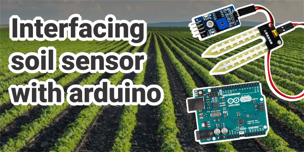
In today’s date, every system is becoming smart like, smart home, smart city, smart classroom and smart irrigation system much smarter system, In this session, we are going to look the key element of a smart garden or smart irrigation system, So Soil Sensor is the backbone of this smart irrigation system, which is useful to measure the moisture of the soil, checks how much dry and how much wet it is.
In the blog, we will discuss, how moisture sensor works and step by step guide of interfacing sensor with Arduino.
The Main Element of Today’s Topics are:
- Introduction
- Technical specification
- How it works
- Interfacing of Arduino
- What are hardware and software requirements
- Programming
- Reference
INTRODUCTION
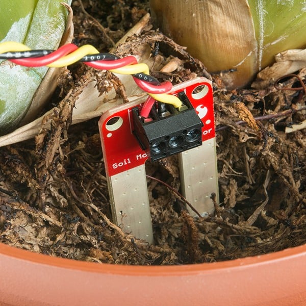
The application of this sensor is to remind the user to water their soil and also monitor the content of the soil. It is used to measure the water content of the soil. When soil is having water shortage it provides high output otherwise the output is low. It has been widely used in the agriculture sector land irrigation and botanical gardening.
Hardware parts:
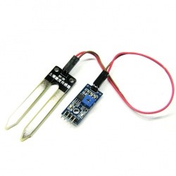
Typically soil sensor consists of two parts:
Probe
It looks like two fork-shaped sensors with exposed conductor dipped into the soil to measure the moisture of the soil. This varies with conditions like more the water content in the soil, less the resistivity, and vice-versa.
The module:
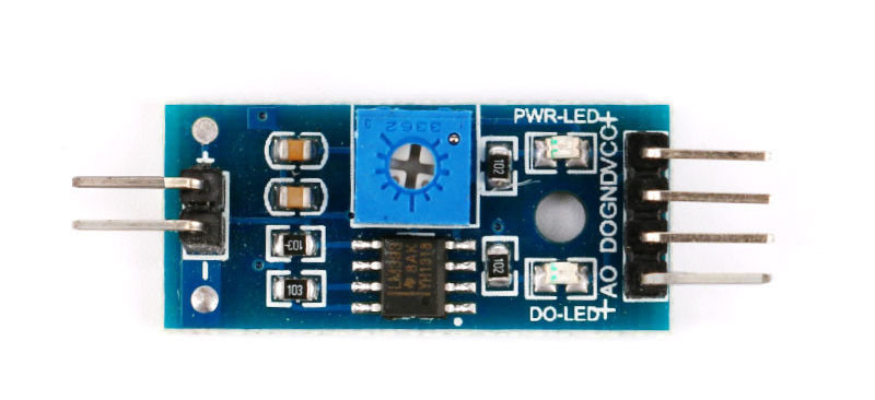
The second part of the sensor is the LM393 module through which the probe is get connected to Arduino. Also this module produces an output proportional to probe, we get this output from analog pin of Arduino. It has an inbuild potentiometer by which we can set its threshold value according to the condition we want.
Technical specification:
How It Works
The working of the Soil moisture sensor is quite simple. The soil moisture sensor consists of two probes that are used to measure the volumetric content of water. The two probes allow the current to pass through the soil and then it gets the resistance value to measure the moisture value. When there is more water, the soil will conduct more electricity which means that there will be less resistance. Therefore, the moisture level will be higher. Dry soil conducts electricity poorly, so when there will be less water, then the soil will conduct less electricity which means that there will be more resistance. Therefore, the moisture level will be lower.
Interfacing of Arduino
The soil sensor comes with both analog and digital output pins, which means we can obtain output in both forms (analog/digital). So it can be interfaced in a two way with Arduino.
Let us see analog one first
Calibration:
For getting the accurate result I first recommend you to calibrate the sensor value with the help of potentiometer, Different types of soil can affect the sensor, so your sensor may be more or less sensitive depending on the type of soil you use.
What is LM393?
The LM193-N series consists of two independent precision voltage comparators with an offset voltage specification as low as 2.0 mV max for two comparators which were designed specifically to operate from a single power supply over a wide range of voltages. These comparators also have a unique characteristic in that the input common-mode voltage range includes ground, even though operated from a single power supply voltage.
Application areas include limit comparators, simple analog to digital converters; pulse, square-wave and time delay generators, wide range VCO, MOS clock timers, multi-vibrators, and high voltage digital logic gates. The LM193-N series was designed to directly interface with TTL and CMOS. When operated from both plus and minus power supplies, the LM19-N series will directly interface with MOS logic where their low power drain is a distinct advantage over standard comparators.
Interfacing in Analog Mode
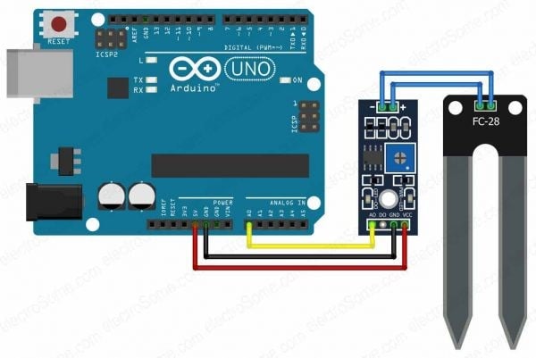
Interfacing in analog mode
In the above diagram, the A0 pin of the LM393 module is connected with the A0 pin of Arduino.The sensor is connected to Electronic module (LM393) which connects the probe to Arduino
As it is seen in the image the pin is connected to 5v of Arduino, GND is connected to GND of Arduino, and A0 pin of comparator module LM393 is connected to the A0 pin of Arduino.
| Soil Sensor | Arduino |
| VCC | VCC |
| GND | GND |
| A0 | A0 |
Arduino Sketch For Analog Reading:
/*******************Demo for Soil Sensor*****************************
Author: Sneha chaware
Note: This piece of source code is supposed to be used as a demostration ONLY. More sophisticated calibration is required for irrigation field application.
***********************************************************************/
const int Soil_Sensor = A0;
int Moisture_val = 0;
void loop() {
Moisture_val = analogRead(Soil_Sensor);
Moisture_val = map(Moisture_val, 0, 1023, 100,0);
Serial.print(“Moist_level: “);
Serial.print(Moisture_val);
Serial.println(” %”);
delay(500);
if (Moisture_val < 50) {
Serial.println(“Soil is Dry, Water it”);
}
else {
Serial.println(“Moisture level is normal”);
}
}
Analog Output:
Interfacing In Digital Mode
Calibration
The module has a built-in potentiometer for calibrating the digital output (DO). By turning the knob of the potentiometer, you can set a threshold.
Now to calibrate the sensor, insert the probe into the soil when your plant is ready to be watered and adjust the pot clockwise or anticlockwise according to glow LED when the moisture level is low. So that users can understand the status of the soil.
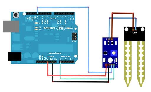
While from the previous example you have to do the same connection except connect D0 pin of the module to pin 13 of Arduino.
| Soil Sensor | Arduino |
| VCC | VCC |
| GND | GND |
| D0 | 13 |
Arduino Sketch For Digital Reading:
/*******************Demo for Soil Sensor*****************************
const int Soil_Sensor = 13;
int Moisture_val = 0;
void setup() {
Serial.begin(9600);
pinMode(Soil_Sensor , INPUT);
Serial.println*********”);
Serial.println(“Reading data from sensor…….”);
}
void loop() {
Moisture_val = digitalRead(Soil_Sensor);
Serial.print(“Moist_Status: “);
Serial.println(Moisture_val);
delay(500);
if(Moisture_val== 1)
{
Serial.println(“Moisture level is low”);
delay(100);
}
else{
Serial.println(“Enough moisture content in Soil”);
delay(100);
}
}
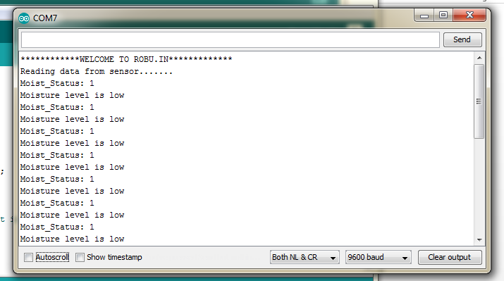
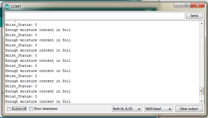
Digital Output:
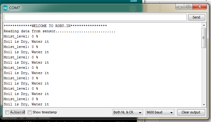
Above Image shows the output for Dry Soil
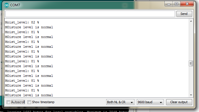
Above Image shows the output for Wet Soil
you can also get this code from here
So this is how the simple project work, if you have any ideas on modification on the paramters and more sensor and actuators we can add to the project to make it more useful, you can mention it in comment section, let your imagination grow and creativity know.
Stay tuned!!!! See you in the next blog, Take care.
You can also check out the following links for more information about each part:

