Secure Your Home with an RFID based door lock Security System Lock With Arduino – Easy DIY Tutorial!
Secure Your Home with an RFID based door lock Security System Lock With Arduino – Easy DIY Tutorial!
In This Blog We Cover Project On RFID based door lock security system with Arduino and Each Details Which is Necessary for This Project. When it comes to adding extra
In This Blog We Cover Project On RFID based door lock security system with Arduino and Each Details Which is Necessary for This Project.
When it comes to adding extra layer of security to your door lock there are many technologies like RFID, finger print identification, facial recognition and keypad code. Among all these technologies, RFID is widely used because it’s more efficient and takes less memory space. RFID stands for Radio Frequency Identification. Basic components of RFID system are RFID reader and RDIF tags. The reader reads the tag’s code and sends it to the controller. Each tag has it’s own unique code which the system identifies and take actions.
How RFID system works?
Initially the RFID reader module transmits high frequency radio waves (in megahertz). The tag consists of a coil (spiral copper track). When the tag is held closer to the reader module. The high frequency radio wave transmitted by the reader induces current in the tags coil. This induced emf powers the chip inside the tag. Once the chip gets powered it transmits the RFID code using frequency modulation. This modulated signal is decoded by the reader and send to microcontroller using standard communication protocols like SPI, UART or I2C.
There are two types of RFID systems. One is active and another is passive. In this project we are using a passive RFID system. In active RFID system, the tag is battery powered and also the frequency is high this increases the range of tag detection to several meters. In passive RFID system the tag doesn’t contain a battery and the range of tag detection is 5 to 10cm which is perfect for our application.
The reader module we are using is RC522. The RC522 module supports I2C, UART and SPI protocol we are using SPI protocol in this project. So lets start with the project.
Components required
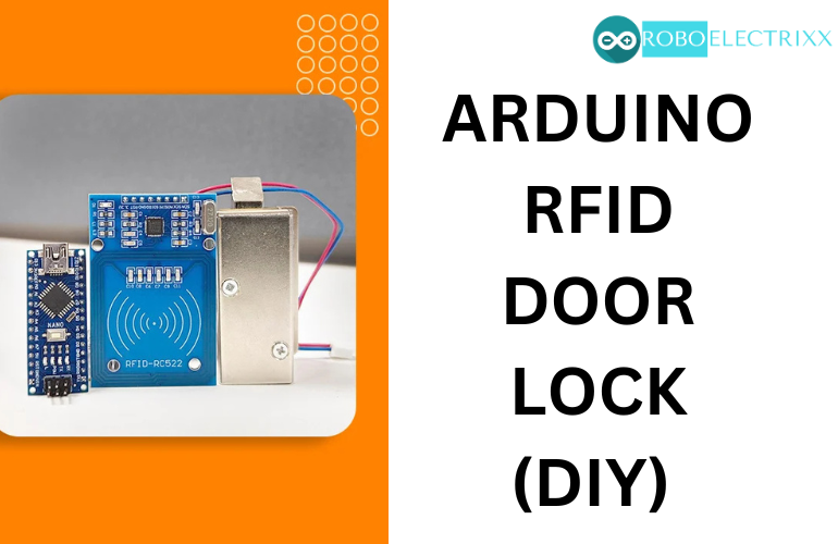
- Arduino nano with USB cable
- RC522 RFID reader module
- RFID tags – 2 tags are available with the module
- Solenoid cabinet door lock. 12V DC
- IRF540 – N channel MOSFET – 1pcs
- 10K ohm resistor – 1pcs
- 100k ohm resistor – 1pcs
- 1k ohm resistor – 1pcs
- 3mm led (orange colour) – 1pcs
- Mini Breadboard – 1pcs
- 12V 5A adapter
- Jumper wires, F to F – 6pcs , F to M – 2pcs , M to M – 2pcs
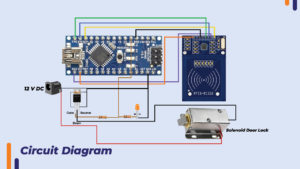
Circuit diagram and explanation

RFID reader connection
The SPI (Serial Peripheral Interface) protocol is used in RFID reader module. So in SPI there are four common pins. They are Serial clock (SCK), master in slave out (MISO), master out slave in (MOSI) and slave select (SS).
The SCK from reader module is connected to SCK of Arduino nano on Pin 13. MISO is connected to pin 12. MOSI is connected to pin 11 and SDA is connected to pin 10 , the SDA is used as slave select pin.
Led is attached parallel to the output of pin 2 which indicates that the card is tapped on the reader.
Why MOSFET is used?
The Arduino nano is programmed to detect a registered RFID tag and turn the output of Pin 2 to HIGH. The output voltage of pin 2 is 5V and also the maximum current it can give is 40mA. The solenoid door lock requires 12V and takes 0.8A current so it cannot be directly controlled by the Arduino. That’s why we need MOSFET to turn on the solenoid as the MOSFET IRF540 can withstand high current (30A) and high voltage (100V). The arduino’s pin 2 drives the gate of the MOSFET. When pin 2 turns high the MOSFET is turned on. This causes the current to flow from source to drain and the solenoid turns on. This retracts the latch and the door is opened.
Code
#include <SPI.h> //library for SPI protocol, SPI is used by rfid reader
#include <MFRC522.h> //RFID reader library
#define SS_PIN 10 // SDA pin on 10
#define RST_PIN 9
#define LED 2
#define NUM_ID 3
//byte readCard[4];
String reg_tag_IDs[NUM_ID] = {"4A6C7E12","D9DB1916","C153FB1D"}; //add tag ids here
String tagID = "";
MFRC522 mfrc522(SS_PIN, RST_PIN); // Create MFRC522 instance
int c=0;
void setup()
{
pinMode(LED, OUTPUT);// initialize LED pin 2 as an output.
digitalWrite(LED, LOW); // turn the LED off by making the voltage LOW
Serial.begin(9600); // Initialize serial communications with the PC
SPI.begin(); // SPI bus
mfrc522.PCD_Init(); // Initialise MFRC522
}
void loop()
{
if(readID()) // check if new tag is tapped
{
Serial.println(tagID); //print tag ID on serial monitor
for(int i=0;i<NUM_ID;i++)
{
if(tagID == reg_tag_IDs[i])
{
digitalWrite(LED, HIGH); // Turn on or off the onboard led
delay(3000);
digitalWrite(LED,LOW);
}
else
{
c+=1; //increment the count if id doesn't matches.
}
}
if(c == NUM_ID)
{
Serial.println("Access denied. ID not registered.");
c=0;
}
else{
c=0;
}
}
}
//Read new tag if available
boolean readID()
{
//Check if a new tag is detected or not. If not return.
if ( ! mfrc522.PICC_IsNewCardPresent())
{
return false;
}
//Check if a new tag is readable or not. If not return.
if ( ! mfrc522.PICC_ReadCardSerial())
{
return false;
}
tagID = "";
// Read the 4 byte UID
for ( uint8_t i = 0; i < 4; i++)
{
//readCard[i] = mfrc522.uid.uidByte[i];
tagID.concat(String(mfrc522.uid.uidByte[i], HEX)); // Convert the UID to a single String
}
tagID.toUpperCase();
mfrc522.PICC_HaltA(); // Stop reading
return true;
}
After the code is uploaded open the serial monitor. Tap your RFID tag on the reader. The four byte tag code will appear on the serial monitor. Copy that RFID code and paste it in the “reg_tag_ID’s” array. Your tag code will be added in the registered tag ID’s. If you have more than one tag then you can add it’s code in the array by separating with a comma. For eg-{“4A6C7E12″,”D9DB1916″,”C153FB1D”}
How many tag Id’s can be added?
As there is limited program memory in Arduino. There is a limit to the tag ID’s that can be added. Each code takes 7 bytes and maximum is 30702 bytes. So according to calculation roughly 3000 tag ID’s can be added.
Conclusion
In this way we made a RFID door lock system using Arduino nano. The door latch opens only when a registered RFID is tapped on the RFID reader. If you have any doubt regarding any part of this blog then feel free to mention it in the comment. Our team will be there to assist you.


