Water Level Indicator: Interfacing With Arduino – Connection and Code
Water Level Indicator: Interfacing With Arduino – Connection and Code
The water level indicator with Arduino is a mini water management system. Here, you will get step by step guide of how to build this water level indicator.
By using this project you will get an exact idea about how much water you should use.

Nowadays, all over India, there is a water crisis. To solve this crisis, we need proper water management on the individual level and we need a water level indicator. By doing water management at the individual level we can save plenty of water and could get rid of the water crisis.
You may have a doubt here about how to do water management individually? Well, it’s simple. All we have to do is to use a little sensor in our water storage system i.e. water tank.
The sensor will give you an indication of the water level in your water tank. If you know the water level every time, you can easily turn your water pump ON/OFF as per the need.
In this tutorial, we are going to interface the water level sensor with the Arduino UNO and we are going to measure the water level of the water tank. If the water level will be low it will turn ON the pump, If the water level is high it will turn it OFF.
Why We Need Water Level Indicator?
This tutorial guides you on how to develop a water level control system. Many times we cannot guess the water level in the water tank from outside, hence we keep the water pump ON. This results in wastage of water. By using this project we can control the water level in the tank.
Also, we can analyze the water level in the tank by the indication with simple LEDs. This helps us to do the water management on our own. By using this tutorial we are not only controlling the water level but also monitoring it. So let’s get started.
.
Hardware Outline Of The Water Level Sensor
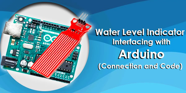
Here, we are going to use a water level sensor to detect water levels. Basically, this sensor is a combination of the attached series of ten exposed copper traces. The copper traces are merged with each other in order to have one sense trace between two copper traces.
In short, there are alternate copper traces and sense traces. These traces form a bridge by water when dipped in the water. For power indication, there is an onboard power LED.
Working Of The Water Level Sensor
This sensor works on the principle of variable resistance. The sensor consists of a series of parallel exposed conductors. Together this series acts as a variable resistor, whose resistance varies according to the water level in the water tank.
As more water sensor is submerged in, the better is the conductivity and the lower is the resistance. The less the water sensor is submerged in, the poor is the conductivity and the higher is the resistance.
The output of the water level sensor is according to the resistance of the water produced. i.e. it will produce a voltage proportional with resistance.
Components Required
Software & Code
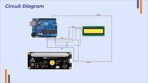
Once your circuit is done, upload the following code in your Arduino software.
To represent our threshold level there are two variables that are used as the Upper Threshold & Lower Threshold.
Below threshold level, red LED will turn on, above threshold level green LED will turn on, in between these two levels yellow led will turn on.
/* Change these values based on your calibration values */
int lowerThreshold = 420;
int upperThreshold = 520;

// Sensor pins
#define sensorPower 7
#define sensorPin A0

// Value for storing water level
int val = 0;

// Declare pins to which LEDs are connected
int redLED = 2;
int yellowLED = 3;
int greenLED = 4;

void setup() {
	Serial.begin(9600);
	pinMode(sensorPower, OUTPUT);
	digitalWrite(sensorPower, LOW);

	// Set LED pins as an OUTPUT
	pinMode(redLED, OUTPUT);
	pinMode(yellowLED, OUTPUT);
	pinMode(greenLED, OUTPUT);

	// Initially turn off all LEDs
	digitalWrite(redLED, LOW);
	digitalWrite(yellowLED, LOW);
	digitalWrite(greenLED, LOW);
}

void loop() {
	int level = readSensor();

	if (level == 0) {
		Serial.println("Water Level: Empty");
		digitalWrite(redLED, LOW);
		digitalWrite(yellowLED, LOW);
		digitalWrite(greenLED, LOW);
	}
	else if (level > 0 && level <= lowerThreshold) {
		Serial.println("Water Level: Low");
		digitalWrite(redLED, HIGH);
		digitalWrite(yellowLED, LOW);
		digitalWrite(greenLED, LOW);
	}
	else if (level > lowerThreshold && level <= upperThreshold) {
		Serial.println("Water Level: Medium");
		digitalWrite(redLED, LOW);
		digitalWrite(yellowLED, HIGH);
		digitalWrite(greenLED, LOW);
	}
	else if (level > upperThreshold) {
		Serial.println("Water Level: High");
		digitalWrite(redLED, LOW);
		digitalWrite(yellowLED, LOW);
		digitalWrite(greenLED, HIGH);
	}
	delay(1000);
}

//This is a function used to get the reading
int readSensor() {
	digitalWrite(sensorPower, HIGH);
	delay(10);
	val = analogRead(sensorPin);
	digitalWrite(sensorPower, LOW);
	return val;
}
Final Words
We hope everyone got all information about the sensor and how to interface it with Arduino. If you found this tutorial helpful let me know in the comment section.
Nowadays, water management is very important for all of us, hope you will use this sensor in your water management systems and refer to this tutorial while doing your project.


